Its a robot which will move by the characters it will receive through bluetooth. You can use any medium for transferring those characters to your robot. Keep in mind that these characters are those which is programmed in our robot, and your robot knows which task to perform when receiving that specific character. We will use an app called "Android Bluetooth RC Car" you can download it from here:
Saturday 1 August 2015
Thursday 12 February 2015
Interfacing LCD with PIC Microcontroller
Hello Guys!
Today I am going to show you how to interface an LCD with PIC Microcontroller using MikroC Pro for PIC.
I assume that you know how to glow an LED using PIC Microcontroller, and you have tried it on hardware as well.
Okay now lets begin:
MikroC Pro has a build in Library code for LCD Interfacing with PIC Microcontroller. Open up MikroC Pro Select new project:


you can download proteus file from here
NOTE: double click on the controller and select the .hex file
Well I have explain in detail about how to burn code in your PIC Microcontroller, in my previous tutorial of glowing led's through PIC Microcontroller

Final result:

Make sure to share this tutorail with your friends so that every one can get the most out of it.
Thankyou!
Regards:
Shahrukh Saleem Qureshi
Today I am going to show you how to interface an LCD with PIC Microcontroller using MikroC Pro for PIC.
I assume that you know how to glow an LED using PIC Microcontroller, and you have tried it on hardware as well.
Okay now lets begin:
Step1 (Writing Code):
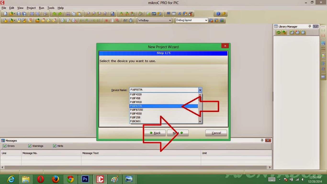
MikroC Pro has a build in Library code for LCD Interfacing with PIC Microcontroller. Open up MikroC Pro Select new project:
A dialog will appear click next:
I am using PICF877A so I am selecting PIC16F877A then click next:
Select a crystal frequency that you're going to use, I am selecting 16MHz, click next:
It will ask the path for saving file, and click next, next and next, copy the code below and paste it in mikroC.
// LCD module connections
sbit LCD_RS at RB2_bit;
sbit LCD_EN at RB3_bit;
sbit LCD_D4 at RB4_bit;
sbit LCD_D5 at RB5_bit;
sbit LCD_D6 at RB6_bit;
sbit LCD_D7 at RB7_bit;
sbit LCD_RS_Direction at TRISB2_bit;
sbit LCD_EN_Direction at TRISB3_bit;
sbit LCD_D4_Direction at TRISB4_bit;
sbit LCD_D5_Direction at TRISB5_bit;
sbit LCD_D6_Direction at TRISB6_bit;
sbit LCD_D7_Direction at TRISB7_bit;
// End LCD module connections
char txt1[] = "Programmed by";
char txt2[] = "Shahrukh Saleem";
//main method
void main()
{
Lcd_Init();
Lcd_Cmd(_LCD_CURSOR_OFF);
Lcd_Out(1,1,txt1);
Lcd_Out(2,1,txt2);
}
Compile your code to generate a .hex file or you can download the .hex file from here
Step2 (Simulation on Proteus):
NOTE: double click on the controller and select the .hex file
Step3 (Burn your PIC using PIC Programmer):
Well I have explain in detail about how to burn code in your PIC Microcontroller, in my previous tutorial of glowing led's through PIC Microcontroller
Step4 (Implement on Hardware):
Final result:
Make sure to share this tutorail with your friends so that every one can get the most out of it.
Thankyou!
Regards:
Shahrukh Saleem Qureshi
Sunday 31 August 2014
Obstacle Avoiding Robot With IR Sensors
Hello, this is my first blog post. Currently I am in 4th semester of Electronic Engineering at Sir Syed University Karachi Pakistan. I wanted to make a robot without microcontroller but I didn't wanted to make an LFR because I already made it as a project of EDC in 3rd semester. So I searched on the internet looked some really cool robots but they included microcontroller programming that I seriously don't wanted to do at this stage. After quite searching I came with the idea of "Obstacle Avoiding Robot". I got the Circuit diagram from http://www.roboticsbible.com here is the photo after completion:


Obstacle Avoiding Robot
Ok LETS MAKE IT...!!
Step 1: (COMPONENTS)
Gather the components:
For IR SENSORS:
1) 1K Resistor
2) 10K Resistor
3) IR Receiver LED's
4) IR Transmitter LED's
5) LM358N OP-AMP IC
6) 10K TRIMPOT
7) 8 Pin IC Logic Chip Socket
8) 3 Pin wire connector
For Main Circuit:
9) IC 7407 Hex inverter IC
10) IC L293D Motor Driven IC
Other Parts:
11) 12V Geared Motor
12) Wheels
13) Sheet for making body
14) Motor holder (Pipe holder)
15) Castor Wheel
16) 2 Pin wire connector
17) Battery
18) Battery holder
19) Switch
20) Jumpers
21) Verroboard
22) Soldering Iron
23) Soldering Wire
Step 2: (MAKING IR SENSOR MODULES)
Ok so we have all the parts in gathered LETS START BUILDING...!!
First we will make IR Sensor here is the CKT Diagram:
CKT Diagram for IR SENSOR MODULE
NOTE: THERE IS A MISTAKE IN THE DIAGRAM THE POTENTIOMETER WILL BE CONNECTED TO PIN 2 AND IR RECEIVER WILL BE CONNECTED TO PIN 3 OF LM358N IC.
I spend hours troubleshooting this diagram since the circuit was not running correctly finally I found the mistake the pin 2 and 3 of LM358N was wrongly connected.
Make two IR Sensors.
TESTING:
Connect the battery, 9V battery can be used doesn't matter. I won't harm the IC LM358N
now move your hand towards the IR receiver the LED on pin 1 should glow when your hand is near IR Transmitter. The IR Transmitter LED should be a little tilted towards the IR Reciever LED, it should not be parallel. So that the Infrared rays transmitted from the IR Transmitter after hitting to an object should be reflected towards the Receiver and hence the LED on pin 1 glows. Notice I used two IR Transmitter LEDS across the IR Receiver LED just for accuracy.
Step 3: (MAKING MAIN CIRCUIT)
Lets make the Main circuit diagram:
Main Circuit Diagram
After building this main circuit connect it to 2 IR Sensor module circuits as shown in figure.
Step 4: (MAKING BODY)
I didn't made the body special, just used single sheet of plastic and pasted the circuit's over it, as shown in figure.
Step 5: (ASSEMBLY)
Assemble all the parts, connect the both IR Sensor Modules with the main circuit. and place it on the body of the Robot. Connect the switch. The IR Sensors should be at LEVEL with the tires as shown
You must be wondering the +5V fixed power supply on the left hand side. When I completed the robot I noticed that the robot was even slow on +9V battery (since I was using 12V Geared motors) so I added another +9V battery. So now I had two batteries both +9V one was new and the other was giving I think 8+ Volt. I added both so I got 9+8 above 17 volt. And now the robot was running with speed.
Step 6: (MAKE A TRACK)
If you want you can make the track I used Sheets of paper as shown in pictures:
ROBOT IN ACTION:
HERE IS THE VIDEO:
https://www.facebook.com/video.php?v=473220692820285&l=4380642576510616884
Subscribe to:
Posts (Atom)